All Products
-
Industrial Pressure Transmitter
-
Low Cost Pressure Transmitter
-
Piezoresistive Differential Pressure Transmitter
-
Piezoresistive Pressure Sensor
-
Liquid Level Transmitter
-
Capacitive Fuel Level Sensor
-
Thin Film Pressure Sensor
-
Infrared Temperature Transmitter
-
Digital Pressure Gauge
-
Digital Flow Switch
-
Magnetostrictive Liquid Level Transmitter
-
Industrial Vibration Sensor
-
Liquid Leakage Sensor
-
Submersible Level Transmitter
-
Magnetostrictive Displacement Sensor
Contact Person :
kenny
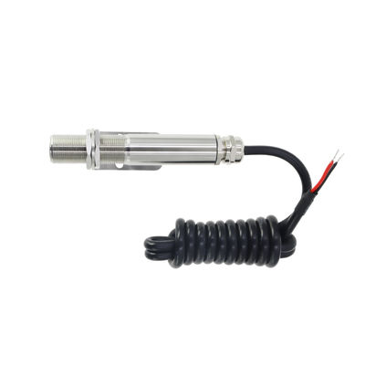
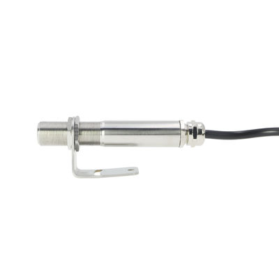
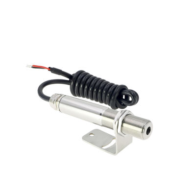
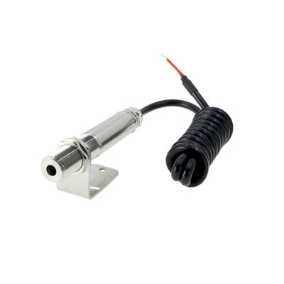
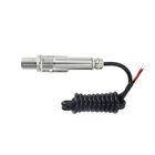
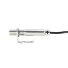
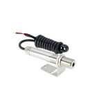
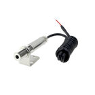
19mm Diameter 4mA Infrared Temperature Measurement

Contact me for free samples and coupons.
Whatsapp:0086 18588475571
Wechat: 0086 18588475571
Skype: sales10@aixton.com
If you have any concern, we provide 24-hour online help.
xProduct Details
| Construction | Stainless Steel | Weight With 1.5m Cable | 180g |
|---|---|---|---|
| Environmental Rating | IP65 | Ambient Temperature Range | 0°C To 60°C |
| Thread | M18x1 | Relative Humidity | 95% Maximum Non-condensing |
| Highlight | 4mA infrared temperature measurement,19mm diameter temperature indicator transmitter,IP65 4mA temperature indicator transmitter |
||
Product Description
Non-contact Infrared Temperature Sensor
Operator’sGuide
ST03 non-contact infrared sensors measure temperature from 0°C to 1200°C and provide a linear 4 to 20mA output. This output signal is compatible with almost any indicator, controller, recorder, data logger ect., without the need for special interfacing or signal conditioning. They are suitable for most materials such as food, paper, textiles, plastics, leather, tobacco, pharmaceuticals, chemicals, rubber, coal and asphalt; but mot materials with low emissivity, for example polished metals. Two-wire CS20L4sensorstransmit thetarget temperatureasa 4-20mA output and offer a simple solution for most applications.
GENERAL SPECIFICATIONS
| Part number | ST03 |
| Measuring range | 0~100/200/250....../1200°C |
| D:S | 20:1 |
| Accuracy | ±1.5% or ±1.5°C(whichever is greater) |
| Emissivity | 0.95(fixed) |
| Response time | 240 ms (90% response) |
| Spectral response | 8 to 14µm |
| Output | 4~20 mA |
| Supply Voltage | 5~30V DC |
MECHANICAL SPECIFICATIONS
| Construction | Stainless Steel |
| Dimensions | 19mm diameter x 113mm length |
| Thread (sensing head) | M18x1 |
| Cable length | 1.5m as standard |
| Weight with 1.5m cable | 180g |
ENVIRONMENTAL SPECIFICATIONS
| Environmental Rating | IP65 |
| Ambient Temperature Range | 0°C to 60°C |
| Relative Humidity | 95% maximum non-condensing |
ACCESSORIES
A range of accessories to suit different applications and industrial environments is available. These may be ordered at any time. The accessories consist of the following parts. Fixed mounting bracket Adjustable mounting bracket Air purge collar Laser sighting tool
OPTICAL CHART
OPTICAL CHART
The optical chart below indicates the nominal target spot diameter at any given distance from the sensing head and assumes 90% energy.
INSTALLATION
The installation process consists of the following stages: Preparation Mechanical installation Electrical installation Please read the following sections thoroughly before proceeding with the installation.
PREPARATION
PREPARATION
Ensure that the sensor is positioned so that it is focused on the target only.
Distance and spot size
The size of the area (spot size) to be measured determines the distance between the sensor and the target. The spot size must not be larger than the target. The sensor should be mounted so that the measured spot size is smaller than the target.
Ambient temperature
The sensor is designed to operate in ambient temperatures from 0°C to 60°C. For ambient temperatures above 60°C, an air/water-cooled housing will be required. Avoid thermal shock. Allow 20 minutes for the unit to adjust to large changes in ambient temperature.
Atmospheric quality
Smoke,fumes or dust can contaminate the lens and cause errors in temperature measurement. In these types of environment the air purge collar should be used to help keep the lens clean.
Electrical interference
To minimize electromagnetic interference or ‘noise’, the sensor should be mounted away from motors, generators and such like.
Wiring
Checking the distance between the sensor and the indicating/controlling device. If necessary, the CS20L4 sensor can be ordered with a longer cable attached.
Models with thermocouple output
When extending the cable, ensure thermocouple extension cable and connectors are used.
Power supply
Be sure to use a 5~30V DC (>25mA) power supply.
MECHNICAL INTALLATION
All sensors come with a 1.5m cable and a mounting nut. The sensor can be mounted on brackets or cut outs of your own design, or you can use the fixed and adjustable mounting bracket accessories.
ELECTRICALINSTALLATION
ELECTRICALINSTALLATION
OPERATING
Once the sensor is in position and the appropriate power, air, water, and cable connections are secure, the system is ready for continuous operation by completing the following simple steps:
1. Turn on the power supply
2. Turn on the meter, chart recorder or controller
3. Read/monitor the temperature.
IMPORTANT
IMPORTANT
Be aware of the following when using the sensor:
1. If the sensor is exposed to significant changes in ambient temperature (hot to cold, or cold to hot), allow 20 minutes for the temperature to stabilize before taking or recording measurements.
2. Do not operate the sensor near large electromagnetic fields (e.g. around arc welders or induction heaters). Electromagnetic interference can cause measurement errors.
3. Wiresmust be connected only the appropriate terminals.
4. Do not damage the cable, as this could provide a path for moisture and vapour into the sensor.
5. Do not open the sensor housing. This will damage the sensor and invalidate the warranty.
Recommended Products


